Creating virtual 3D models, this framework conceives as a series of elementary operations embedded in Python code. Interactive modeling using application tools can be fun, but mostly only until the moment when similar operations need to be repeated over and over again. Then it is more advantageous to record the operation into a "macro". The drawing program records a series of operations, which can then be applied. This option has its disadvantages. We are dependent on how the drawing program handles macros, how we can modify them, and how their codes are understandable to us. Because we are not perfect, we make mistakes even when drawing a model, but if it is an error that can be easily corrected by interactive intervention, it is not a problem. However, if there is an error in the overall design concept, its correction is laborious. Often, in an attempt to make our work easier, we will correct errors with further mistakes, "wedge wedges", until we are satisfied with the imperfect result. So why not define something similar to macros, but much more clearly under our control right from the very beginning of the design? If we have the whole process defined methodically and completely in the code, there will be no problem to modify any rule and let the program do all the work from start to finish for us. The mistake will no longer be a mistake, but only a bad rule that we will correct at the very beginning and, above all, anytime. We will have almost unlimited possibilities of optimizations and creating our own methods, rather than being limited only to the interactive methodology of the drawing program. For greater clarity, here is an example of how to generate the desired model completely using code through the application FreeCAD:

demo0.py
The example demo0.py along with the modules tree.py, freeCADTree.py, and piping.py (demo0.zip) needs to be placed in the folder
where FreeCAD expects user modules. This can be found out in FreeCAD: "Macro -> Macros -> Location of user macros:".
On Linux, it will be something like ~/.local/share/FreeCAD/Macro. In Windows: C:\Users\<User>\AppData\Roaming\FreeCAD\Macro.
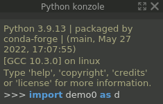
We run the example as an imported module with the command import demo0 as d from the "Python console" panel of the FreeCAD application. If the panel is not displayed, it can be displayed: "View -> Panels -> Python console".
The module will generate the required objects and insert them into a new FreeCAD document, which it will create itself.
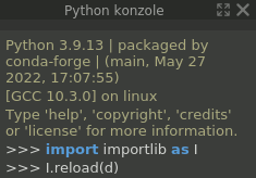
For repeated execution, it is necessary to execute the commands import importlib as I and I.reload(d).
This is necessary, for example, after modifying the module (with a text editor) or when needing to generate a new document again.
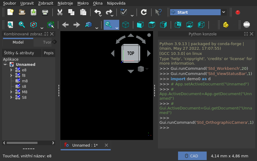
Structures generated into the document:
- e8
- edges of facets in the context of an octant (facets) and the 3D axis on which the first vertex lies (the second is on the next 3D axis) - an ideal basis for further constructions; it practically represents an octagon
- f8
- facets created from 3 edges each
- m8
- network of edges - the skeleton of an octagon; already without the "xyzd" context and duplicates - a basis for further constructions derived from this shape
- s8
- body of facets - octagon with solid walls
- M8
- embodied components of the m8 shape - enveloped with a mass of radius
J.r; from facets come prisms, from edges come tubes, and from nodes come spheres - S8
- --||-- s8 --||--
All these structures will be visible in the "Combined View - Model" panel (click on the name, spacebar),
but also as attributes of the module, accessible from the "Python Console" panel, where you just need to write the name of the attribute (e.g., d.e8 or d.f8).
All other attributes of the module that do not have an alternative in the document (e.g., d.o8 or d.c8, etc.) are also accessible from the console.
Objects that are accessible interactively from the console can be easily examined in every aspect, primarily as native objects offered by FreeCAD and integrated modules.
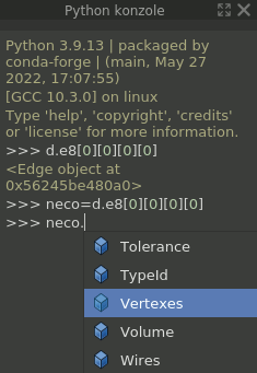
Just type a dot after the attribute name and the console will offer all attributes of the object, including methods that can be used in the console immediately - executed as a Python command.
In fact, all objects contained in the application or document can be interactively examined.
For examination from the console, the most interesting series of auxiliary structures preceding the structure e8, which are not inserted into the document, will probably be pl, o8, c8, v8, vr8, vv8, described in comments directly in the module.
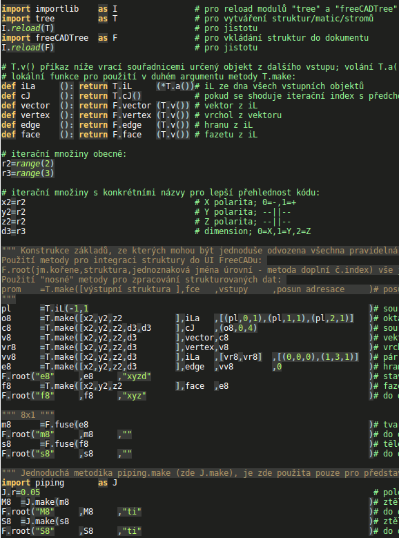
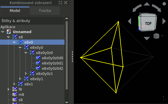
The example demonstrates the complete process of generating a FreeCAD document with all steps, the results of which are accessible through module attributes, so that the entire process can be examined and any errors can be found.
Writing similar code proceeds by gradually adding elementary operations over entire structures of objects until the goal is achieved.
The development of a 3D model may initially seem complicated, but after adopting the methodology of the working framework, it can be much more "fun" than just interactive modeling, because the modeler becomes both a programmer and a methodologist.
Frustration from any errors in the 3D model completely disappears, because they can be eliminated only by changing the methodology, which the developer has fully under control.
The example should end correctly by creating the structure e8, because it can be used in several scenarios, the most interesting of which will probably be the derivation of other geometric structures.
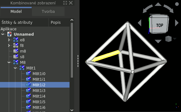
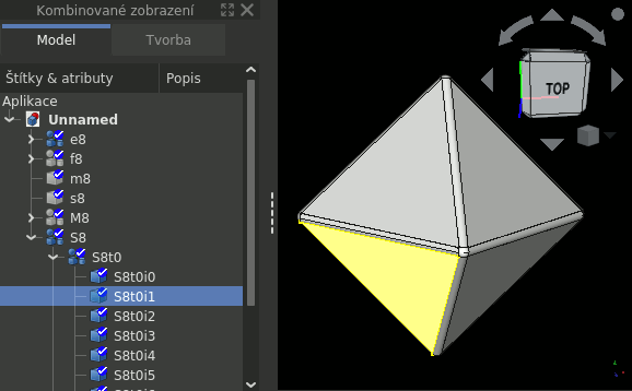
Structures M8 and S8 serve only to demonstrate some simple but illustrative result of all operations.
By merging all components (e.g., fM8=F.fuse(M8)), we would already get a usable body and
if we wanted to use it interactively, we could place it in the FreeCAD document with another command F.root("fM8",fM8,"").
In the example, the standard module importlib is imported, which is part of the Python distribution and is used only to reload modules with state data.
Three modules from our workshop are also imported, which follow on from the modules of the "FreeCAD" package and add the methodology of the working framework:
tree.py
Defines the iL object, extending the native list object and adding further methodology for working with tree structures.
Its most used method is make, which processes input structures and creates output structures.
Both input and output structures resemble matrices, which is why the use of the method is sometimes simplistically called a "matrix" operation.
To understand how to use the method, it is advisable to open the example in a separate window, preferably in a text editor.
If we unpack the files into the directory where FreeCAD looks for modules (see the first paragraph under the heading "demo0.py"), we can immediately try everything in practice.
The cases described later can be found in the demo0.py file at the T.make commands.
The dimensions of the output structure/matrix are defined by the first argument, according to which iterations are also performed when calculating its values.
Values are calculated by the method specified in the second argument. Input structures/matrices are listed in the third argument.
If more than one structure is used, it is necessary to provide a list, for example, [pl,pl,pl].
If the input structure/matrix has different dimensions than the output one, it is necessary to specify which ones.
For this purpose, it is necessary to "wrap" individual inputs into "tuple" parentheses, where the first element specifies the actual input structure,
the second specifies the dimension number, and the third specifies the number of dimensions by which the structure should be addressed.
For example, the definition (pl,0,1) means that the values addressed by the coordinate of the zeroth dimension and only this one should be used from the pl structure.
The fourth argument defines the shift of addressing the input value in the matrix. This is useful if we have two input structures/matrices and for the calculation of the output value, we need a value from each of them at a different coordinate.
The shift must be specified as relative to the output dimension.
For example, the argument [(0,0,0),(1,3,1)] means that the first input matrix should be used normally (only syntactic filling), but for the second one, the coordinate should be shifted by +1 at the third dimension.
And it should only apply to this one dimension (indicated by the last digit 1 in the tuple).
The third, fourth, and fifth (not used in the example) argument of the make method have the same syntax. If its value applies to all dimensions, it is specified directly.
If we need to use the value only for certain dimensions, it is necessary to wrap the argument into round brackets and specify the value, comma, dimension number, comma, and the number of dimensions for which the value should apply.
freeCADTree.py
Creates an interface between native modules and custom methodology or other custom modules of the working framework.
The custom methodology is primarily used to integrate created structures into FreeCAD application documents.
After its import with the command import FreeCADTree as F (in the example above), we can, for example, set its attribute F.Vi=True,
which indicates that the F.root method will insert objects into the document as visible. The default value is False.
piping.py
A very simple module used only to "wrap" elementary shapes with material using the make method.
The method takes all facets, edges, and vertices of the specified shape and "wraps" them with material of the radius set in the r attribute.
The method returns a structure of three lists: prisms from facets, cylinders from edges, and spheres from vertices. If we want to merge all these bodies into one, we can simply use the fuse method of the freeCADTree module.
demo1.py
Another example builds on demo0.py. It adds code that derives structures from prepared ones, consistently preserving the context of the structure. Specifically, it is about the construction elements of the dual body to the octahedron, which is a hexahedron - a cube.
In general, a dual body can be easily derived from the midpoints of the faces of the original body, where we place the vertices of the dual body.
It is not necessary to maintain the exact length of the vector, but only its direction is sufficient. On this "vector" line, we can then place a vertex at a distance from the center of the body exactly according to how large the dual body should be.
If we leave the vertices as far away as the faces of the original body, the dual body will be inscribed in it.
The vertices of the dual body can also be placed at a distance from the center, so that their lines/edges will intersect the edges of the original body at right angles.
From such a connected network of edges, it is then possible to generate a "pipe construction kit" which will already contain both bodies. The calculation of the size of the dual body and its construction is included in this example.
At the same time, in the example demo1.py compared to demo0.py, there are also several additional functions and details. After downloading (demo1.zip), it is necessary to unpack the archive into the directory mentioned in the previous example.

