For most people, it's no secret that alongside the real world we can physically touch, there also exists a virtual world. Sometimes, it's necessary to have objects from our real world also in the "computer" so that we can perform some of the tricky tasks that aren’t possible to do outside of it. Virtually, we can manipulate objects in almost any way. We can transform objects into the virtual form using various techniques, depending on object’s regularity.
Virtualization
Programmers usually introduce regularities into the computer. Irregularities need to be interpreted from real world and registered into the computer by scanners or modelers. In any case, we can have a virtual representation of anything from the real world, as long as we can model, scan or generate it. We can do that with any type of the object - texts, dimensions, relationships, 2D or 3D objects.
This project is focused solely on 3D objects, primarily regular constructions that can be made using specialized library programming methods created specifically for this purpose. The project conceptualizes regular constructions from two main perspectives. One is the general creation of any construction that can be algorithmized in some way, the other is the creation of standardized models, building blocks, from which larger constructions can be built.

The fundamental standard of 3D modeling are 3D networks - points placed in 3D space connected by lines. In 3D space, lines are usually referred to as "edges" and points as "vertices" ("nodes" in network terminology). Three vertices connected by three edges are called a facet. The entire 3D virtual object in the computer is usually assembled from triangular facets. It's a very simple principle on which practically the entire virtual 3D world is built. 3D networks can represent tangible objects by defining the surface - a boundary between the material and it’s surroundings. They can also represent non-closed (volumeless) surfaces, or just the essence of 3D networks, which is the network of nodes and edges.
Materialization
When we talk about 3D printing, we usually imagine materializing a virtual object, most likely a closed 3D network, where the 3D network dictates where to print (fill with material) and where not to. However, usually we are only interested in the surface, which represents the materialized object, and the volumetric component is not as significant to us. We are mainly interested in what the object looks like. Commonly, various infill structures are used, only to support the surface shell, allowing it to maintain its shape. As for the sturdiness characteristics of the object, they are usually not heavily calculated, as it is too complex. If needed, a different infill is chosen and the object is tested. For a more precise calculation, the infill would also need to be conceived as a network that meets the structural requirements of the object.
Small-sized objects can be fully produced using some current 3D printing technologies. As the size of the object increases, production becomes more challenging and it is necessary to divide the object into parts. With an increasing number of parts, the overhead for division, production, and subsequent assembly grows. If there are many parts, it is necessary to establish a rule for how to divide the object and then reassemble it in its physical form (building kit principle).
It is advisable to build principles from the most simple/basic to more complex ones. Therefore, using 3D mesh objects as the foundation for building is suggested as an ideal approach. It is essentially a view of real objects from the other side, not as a portioned and glued whole, but as a construction of a whole from elementary parts derived from a 3D mesh. We can also view it "building kit style" through the strength requirements of objects, which can be directly reflected in the mesh because mesh construction hasrelatively simple (vector) "mathematics". And sometimes, we can completely ignore the surface shell (facet fill) if it does not have a significant impact on strength. 3D mesh, like a building kit, requires a certain standardization, but it brings a huge benefit of modularity, scalability and universality, just like any building kit system (1). The universal principles used for assembly also simplify potential disassembly and the reusability of parts, which can lead to a reduced need for basic materials and ultimately to a smaller carbon footprint of industrial production.

Every technology has its limitations. In 3D printing, this is primarily limited by gravity and the dimensions of the product, which must fit within a certain space. When producing elementary components of the building set, we can address these limitations more systematically and optimally than with complex objects. Building systems allow us to bring into reality objects for which there is currently no available alternative or they are too expensive. The advantage of edge and node building sets is that edges can be produced simply by perpendicular cutting of rod/tubular material to the desired length. Nodes (so-called connectors) will "take care of" everything else. 3D printing is ideal for nodes, primarily due to standardization already at the level of their basic construction and a wide variety of typed parts. For more regular constructions and serial production, older casting technologies (with the production of a mold based on the generated template) may also be considered.
Nodes (connectors) can be generated automatically based on several basic parameters. Primarily, these are the parameters of edges and the requirements for the strength of connections. Edges converge at vertices at various angles, and based on their parameters, they predetermine how the connectors will need to look. Hollow edges (tubes) will probably be best connected with an internal pin. This pin can also be parameterized (number of lamellae, size of the overflow, thread, etc.). Solid edges must enter the node. The outer shape of the node will be determined by the edge with the largest radius. The radius of the node can be explicitly set larger, resulting in a spherical overflow (similar to modeling an atom). 3D meshes with edge parameters are input into the building set generator. The generator then creates unique objects by connecting all the meshes together and calculating how the nodes should look with a definable tolerance. In other words, since the mesh construction can be composed of many connections, they need to be standardized (normalized) in some way. This can be achieved through an adjustable tolerance. Too small a tolerance will result in many types of connectors. Too large a tolerance, on the other hand, will cause deformation in the resulting construction. In "straw" models, a deviation of a few degrees in edge angles will not play a significant role. For regular models (e.g., generated ones), it is possible to use an almost zero tolerance because the morphology of the parts is the same. All these aspects are already taken into account in the project.

Today's technologies, which prepare virtual templates, naturally standardize in the form of data formats (e.g., STL), universally accepted approaches, and software tools. The standardization of other generalizable principles of using mesh constructions, in the form of software methodologies (objects/modules), can retroactively support the development and integration of manufacturing technologies. This is one of the additional benefits of the building block system, which can elevate the principles of the 3D mesh to a higher utility level and integrate established and relatively inexpensive technologies with the potential for further development.
Primary Motivation:
- Tarpaulin sheds, tents
- Trackers for celestial objects (with real axes)
- Minimalistic constructions serving only a basic purpose
- Building block systems in general


Requirements:
- Universal concept for converting 3D meshes into a building block system for constructing real 3D structures.
- Generation of ideal parts with the desired strength characteristics. Primarily, these are edges that are intended to exhibit a given strength (tension, compression). Secondarily, these are nodes/vertices that are meant to connect these edges.
- The system should be open in terms of:
- manufacturing technologies for the parts - technologies should be applied gradually with consideration of their availability.
- expandability to any constructions (including flexible joints).
- future development.
Selection of Available Technologies
Software Requirements:
- potential for open scalability,
- high degree of automation,
- educational potential (documentation, information resources),
- economic accessibility.
Software Choice:
- System based on open technologies in a Linux distribution (without excessive marketing influences).
- FreeCAD + Python libraries as the most suitable tool for testing and generating parts, considering its availability and nature.
- Python as the most suitable language for developing necessary technologies, given the modules used and the possibility of deploying the system as a mere "backend" application.
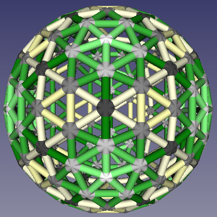
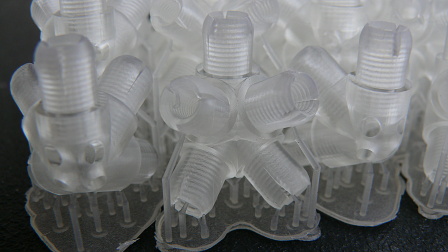
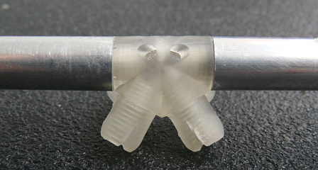
Development of Partial Supporting Technologies (Python):
- Extended list class with rich universal methodology (value retrieval, shifts, permutations, indexing, and more).
- Working with multi-dimensional structures - matrices/trees - universal methodology for iterative processing of various data structures.
- Integration of working with data structures and FreeCAD modules as its superstructure.
- Custom mesh objects supporting the system's concept - nodes, edges, joints, angles, which can be indexed and grouped by similarity (with scalable tolerance) with calculation of differences (different rotation, placement, etc.).
- Production of partial structures into the FreeCAD application environment for interactive research and verification of partial results (any partial result can be interactively used with standard FreeCAD tools).
- Production of several final construction structures, e.g. groups of unique parts for production with necessary attributes, including lists of their occurrence and precise placement in the final product.
- Support for 3D printing - Currently involves optimal orientation and adjustment of models to eliminate possible printing errors. Generation of supports and pre-print preparations are still done "manually".
- "Tubing" of meshes for simple previews of final products.
- Methodology for constructing regular polyhedra for case studies and system testing.
- Custom module for generating "locks"/cavities of joints (threads, etc.).
- Other supporting methodology, not specified in detail.
Hardware Requirements:
- Common 3D printer for basic parts.
- High-resolution 3D printer, ideally based on a lithographic principle for more detailed parts.
- PC meeting the requirements of the Linux distribution.
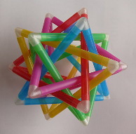

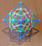
Currently, the project is in the testing phase. Regular polyhedra are used as mesh models, while plastic straws are used as real edges and nodes are printed from resin using a 3D printer. For more robust constructions with potential real use, aluminum tubes and printing from higher-quality materials allowing for the application of locks are chosen. Nylon strings are used for "tensile" edges. The project is also a way to explore limits - in size, material, and technology. For constructions with moving parts, a system of joints, rotational axes, and edges with dynamic length is under development.
- An illustrative example of a similar principle is the well-known toy, a building set for children, with which one can assemble fairly robust and complex creations. It is based on the simple principle of connecting plastic blocks. This is a great example of standardizing universal parts. Given that the building set is primarily based on "rectangular" joining and layering of building blocks, assembling more complex shapes requires using a relatively large number of parts. Building block systems that depart from this conservative approach may find much wider applications.

